


New Plastic Extrusion Plants
The system consists of a series of elements, connected to each other, in order to guarantee perfect operation in full compliance with the regulations in force regarding safety for the operator and the surrounding environment (Machinery Directive 89/392 EEC, 91 / 368 EEC, 93/44, 93/68 EEC).
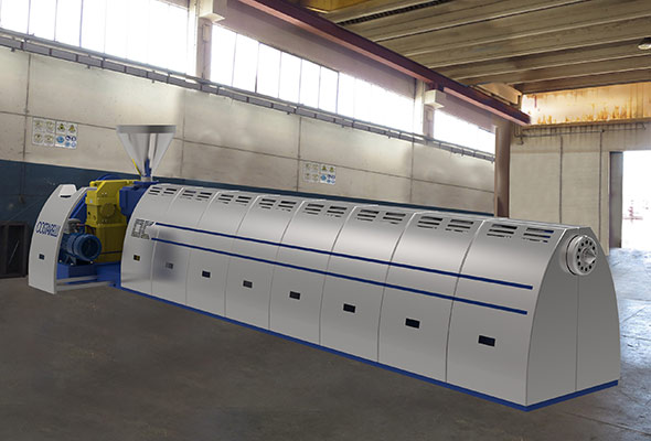
The extruder essentially consists of a cylinder and a screw that rotates inside it. During operation, the introduced material is plasticized thanks to the heat supplied by the electric resistances (placed around the cylinder). The steady-state regulation of the temperature is entrusted to the resistances and fans which, by intervening periodically, keep the temperature constant in each area into which the extrusion cylinder is divided.
During processing, the elimination of volatile substances (produced during processing) takes place by means of a double degasser.
Description of the main components of the machine
- The base is made up of electro-welded sheets; the motor, the reducer and the extrusion cylinder are mounted on it.
- The motion transmission, from the motor to the gearbox, takes place by means of V-belts protected by special casings bolted to the structure.
- The electric motor is of the direct current type and allows, as the load applied to the axis of the machine varies, a proportional increase in current and therefore an adequate variation in the number of revolutions of the extrusion screw in different operating conditions.
- The gearbox is of the parallel axis type made with case-hardened, tempered and ground steel gears protected by a cast iron casing. The reducer is equipped with a connection bell, by means of which it is coupled to the extrusion cylinder; an axial roller bearing, orientable, is mounted inside the bell, capable of neutralizing the axial load of the extrusion screw.
- A forced lubrication system with heat exchanger is applied to the gearbox. This ensures continuous lubrication of the bearings and maintenance of the temperature within the values set by the manufacturers of the lubricants.
- The extrusion screw is made of special heat treated, nitrided and ground steel, it is responsible for the transport of the material to be extruded.
- The extrusion cylinder is made from a special nitrided steel tube with a ground internal surface.
- The degassing chambers have the task of eliminating the air and / or gas that develops, during processing in the dough, before being cut.
- The cylinder is heated in zones and is achieved by means of electrical resistances (band) mounted around the cylinder, which are insulated with ceramic material and covered with a casing for the protection of the personnel in charge and for heat recovery. Each casing is made up of a reflective stainless steel sheet.
- Cooling is required in several places on the machine:
– in the areas along the cylinder, by means of fans, controlled by the control panel, this allows correct regulation of the amount of heat necessary for processing the material;
– in the feeding area of the cylinder through a water cooling system;
– in the gearbox oil heat exchanger; - The water used for cooling is not contaminated, so it can be discharged or recycled without undergoing purification treatments.
- The control panel (IP 54) consists of a metal cabinet in which all the electronic components of the machine are placed, it is equipped with keys (for safety) which must be in the possession of highly specialized personnel. In addition to the usual control devices (extruder Start and Stop buttons, an ON / OFF selector for the heating zones and one for the degassing system), the control panel also includes system control devices (connected digital and analog devices with the respective measuring instruments: pressure transducer in the head, an extruder screw revolution counter and, for each heating zone, an amperometric probe and a temperature sensor) and safety (emergency button, an alarm siren for maximum head pressure). A PLC automatically manages the start-up and shutdown of the extruder in a sequential manner.
- The loading hopper is made with a shaped sheet metal anchored to the manifold by means of a series of screws.